Tuesday 29 September 2009

Victorian Bell System - Winchester Bell Pull / Fitting

Tools Required
Drill - 6, 8 and 10mm masonry drill bits - Scissors - Small hammer - Slotted screw driver - Spirit level - Small round file - Junior hacksaw

Before you start
1. Decide upon the height and location of your external Winchester Bell Pull and Internal Butlers Bell
2. The screws and wall plugs supplied are only suitable to use in solid walls. If fitting to other types of wall please source suitable fixings from your local hardware store.
3. Ensure there are no hidden service pipes or cables where you intend to drill.
4. The external fittings MUST be fitted first. 

Fitting Instructions 
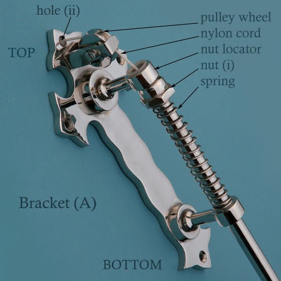
Step 1 - Unscrew nut (i) located on the top of  bell rod and remove bracket (A)
Step 2 - Mark the position of the four holes in bracket (A) on the brickwork
Step 3 - Hole (ii) in bracket (A) allows your bell cord to pass through the brickwork. Drill this hole using a 10mm drill bit. Step 4 - The remaining three holes are used for fixing bracket (A). Drill these with an 8mm bit to a depth two millimetres deeper than the length of the wall plugs provided. Tap the wall plugs into each of these holes. Before securing bracket (A) with the screws provided, pass the cord through the hole in the top of nut (i) and tie a knot in end (cutting off any excess) so the cord is now captive inside the nut. Continue to feed the loose end of the bell cord through the nut locator, over the pulley wheel, through the hole (ii) and the brickwork. When most of the cord has gone through the wall, wrap the remaining cord around the pulley wheel bracket at the top of the bell rod to stop it being pulled back through. Secure bracket (A).
Step 5 - Re-assemble the bell handle, spring and nut removed in Step 1.
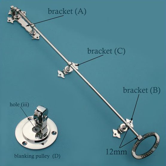
Step 6 - Position bracket (B) approximately twelve millimetres above the square shoulder of the bell pull handle. Mark the location of the two fixing holes. Drill the holes using an 8mm bit. Plug and secure with screws provided.
Step 7 - Position bracket (C) mid-way between brackets (A) and (B) and repeat fixing procedure. 
Step 8 - The brass tube supplied acts as a liner in the brickwork and helps protect the bell cord from dust. From inside the house, feed the cord through this tube and push it hard into the hole so it meets bracket (A). Mark the tube where it emerges from the wall. Remove the tube and cut it to length. Replace the tube ensuring that it sits flush with the inside of the wall and does not protrude
Step 9 - Thread the bell pull cord through the hole (iii) in blanking pulley (D). Place the blanking pulley in position over the hole, ensuring the wheel of the pulley is running in the right direction and that hole (iii) is central to the brass tube. Mark the position of the three fixing holes and drill with 6mm bit. Plug each hole and secure the pulley with the screws provided

If you order our Internal servants bell it is supplied with an extension pulley and directional pulley, extra pulleys are available as separate items. 

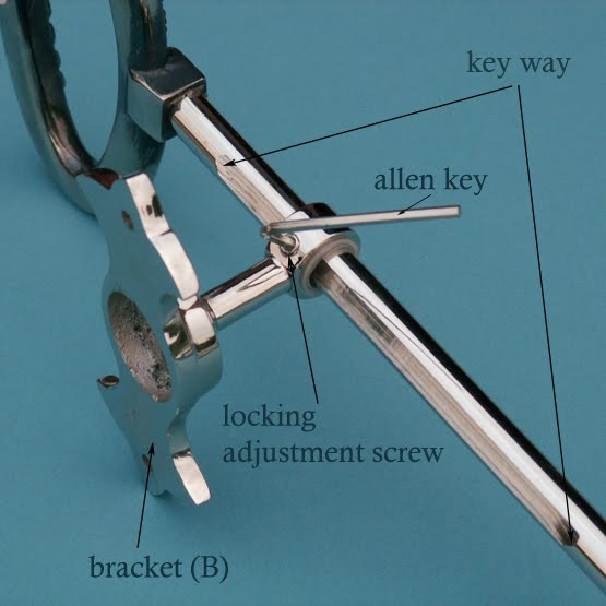
There may be occasions that you want to lock your bell pull - may be when you go on holiday. You can do this by tightening the grub screw located on the side of 'Bracket B' (see in photo opposite) using the Allen key supplied but remember that adjusting the screw in or out will affect the smooth running of the rod.

Sunday 27 September 2009

Rim Latch Emergency Release - Fitting

Parts List
Rim Latch and keep – Screws - Emergency release catch

Tools Required
Drill – 12mm & 7.5 drill bits – Slotted screwdriver – Rule/ tape measure – Pencil – Junior hacksaw

Fitting Your Lock
Step 1 – Decide exactly where you intend fitting your rim lock or rim latch and offer it up to the edge of the door. Check to see if there is sufficient clearance between the door and door frame to allow you to secure the lock. Let return of lock into edge of door, as necessary.
Step 2 – Mark the centre of the square hole required for the door knob spindle using a pencil. Drill this hole using a 12mm drill bit.
Step 3 – Offer the lock back up to the door and fit your spindle and door knobs. Secure your lock to the door using the screws provided.
Step 4 – Close the door and mark the position of the keep on the door frame. Let the keep into the architrave / frame as necessary, ensuring that the thumb latch is able to slide into the keep. Secure using the screws provided.

Fitting the Emergency Release
Step 5 – Carry out steps 1-3 above, then remove the rim lock from the door and place it face down on a clean flat surface  
Step 6 – Fold the tracing paper template (provided) towards you, along the dotted line. Place the template no the back of the lock, ensuring that it sits accurately over the pre-drawn line. Mark the centre of the square spindle hole, all the screw holes and the emergency release slot on the tracing paper.
Step 7 – Now place the template tight up to the edge of the door in the position previously occupied by your lock. Ensure that the template is the right way up and that both the spindle and the screw hole centre marks line up with the holes you have already drilled. Check, re-check then mark the centre of the emergency release slot on the door, through the tracing paper. Drill this hole using a 7.5 mm drill bit.
Step 8 – Cut your emergency release bar to the correct length – allowing for BOTH the thickness of you door and the section of bar that needs to be located inside the slot in the back of the lock. 
Step 9 – Push the emergency release bar through the hole you have drilled in the door (from the opposite side to the lock). Place the round emergency release cover plate over the slotted end of the bar and secure using the two screws supplied. Offer the rim lock up to the door, ensuring that the release bar locates in the slot on the back of the lock. Secure the lock using the screws provided and fit your door knobs
.Step 10 – Check that your emergency release works. (Please note that your emergency release ONLY operates to pull-back the catch, not the other way around – that is to say that you can’t lock the door using the emergency release). 

Your rim lock and emergency release is now ready for use.

CLEANING
Spray periodically with a good quality furniture polish and dust with a soft, dry, clean cloth. (N.B.) Cast iron rim locks are sprayed with silicone to protect them from moisture. You may wish to remove any excess spray with a dry cloth or tissue before fitting. Cast iron locks should NOT be used externally or in very damp conditions)

These fitting instructions are the same for all of our rim locks and rim latches, bearing in mind only the latches have the emergency release.